On this page:
- System overview
- Sensors
- Inference Engine
System Overview
The Omnicept system is a wheel-and-spoke architecture with two main components.
- A Omnicept runtime acting as a local server to process and route sensor data among Omnicept clients.
- Various Omnicept clients that connect to the runtime and send or receive sensor data (including inference engine messages).
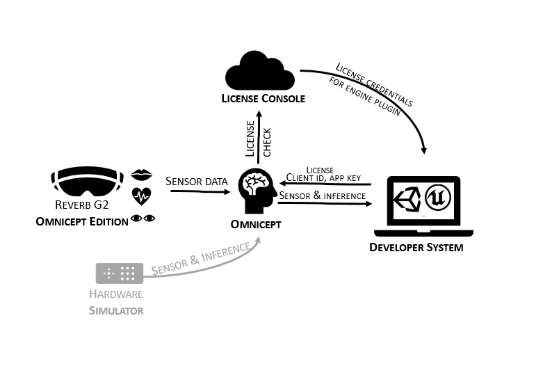
To access Omnicept data, you will require an Omnicept license. Licenses are acquired through the Developer's Console. An account must be created on the Developer's Console to create the client and access keys credentials used in the Omnicept enabled solution. This client and access key confirms with the Omnicept service that the runtime is licensed to get inference engine information.
Omnicept runtime
The Omnicept runtime is a system designed to connect sensors to applications running on a single PC. The runtime transports compact datagrams between Omnicept client processes. The runtime also hosts internal modules (on Windows, .dll files) that read and process incoming sensor data.
The Omnicept runtime contains two major components:
- A Windows service named HP Omnicept . When running, this service ensures svc-core.exes started.
- A process named svc-core.exe. This process provides datagram routing between clients.
Omnicept Clients
A client is any process that connects to the Omnicept runtime. Omnicept client code may be written using the C++ or C# Omnicept APIs, exposing functionality to connect to the Omnicept runtime as well as create, send, and receive sensor datagrams. Datagrams sent by a client will be received by every other client. The runtime guarantees that datagrams sent by each client are received in the order they are sent. However, datagrams sent by two-or-more different clients are not guaranteed to be delivered in a certain order to a third client.
From Omnicept 1.11 clients have the possibility to choose which messages they receive and the version of these messages. To do so a Subscription List containing all the desired messages and versions is required.
Clients included in the SDK
The Omnicept SDK comes with two full clients:
- Omnicept_simulator.exe, which generates simulated sensor data, and;
- Omnicept-console.exe, which can print data to a command prompt for debugging purposes.
Sensors
The Reverb G2 Omnicept Edition has a set of sensors that are exposed through the Omnicept SDK. In order to understand better the possibilities of integrating these sensors, we will review each sensor description and their outputs.
Eye Tracking
Sensor Description
Cameras pointing at the user's left and right eye. The eye camera and eye-tracking on the HP Reverb G2 Omnicept edition is powered by Tobii
Outputs
-
EyeTracking::Combined Gaze Vector: 3D unit vector describing where the user is looking in x, y, z for a right-handed Cartesian coordinate system. Omnicept only provides combined left and right eye gaze.
-
Units= None. X, Y, Z are are normalized components of a unit vector.
-
Range: [0,1]
-
Reporting Rage: 120Hz
-
-
EyeTracking::Eye::Pupil Position: Position x,y of the pupil within the field of view of the eye tracking cameras. Reported for left and right eyes.
-
Units: None; values are normalized to camera sensor area.
-
Range: From the perspective of the eye camera, normalized values range from top left (0,0) to bottom right (1,1).
-
Reported Rate: 120 Hz
-
-
EyeTracking::Eye::Pupil Dialation: Approximate pupil diameter, reported for left and right eyes.
-
Units: Millimeters
-
Range: 2 – 8 mm (float)
-
Reported Rate: 120 Hz
-
-
EyeTracking::Eye::Openness: Detects if eye is open or closed. Reported for left and right eyes.
-
Units: Boolean
-
Range: 0 or 1
-
Reported Rate: 120 Hz
-
-
Confidence Values: A Boolean representing if the respective field is valid.
-
Units: Boolean
-
Range: 0 or 1
-
Reported Rate: 120 Hz
-
Caveats & Limitations
- If the eye is not detected by camera sensors, values for each numerical field are reported as -1.
Heart Rate
Sensor Description
PPG (photoplethysmogram) sensor detects the blood volume changes in the microvascular bed of tissue using light signals that reflect onto the skin. The PPG sensor is located on the forehead, represented by two green LEDs. HP does not provide access to the raw PPG data. Why?
Outputs
The PPG reading provides the following outputs:
- Heart Rate:
-
Units: Beats Per Minute (BPM)
-
Range: 40 to 350 (int)
-
Report Rate: Once every 5 seconds
-
- Heart Rate Variability:
-
SDNN: Standard deviation between two normal heartbeats
-
Units: Milliseconds
-
Report Rate: Once per minute
-
-
RMSSD: Root-mean square of successive differences
-
Units: Milliseconds
-
Report Rate: Once per minute
-
-
-
PPG Requires a special agreement in place, PPG is not enabled by default
-
PPGFrames - A ppg frame has a series of PPGs. Each ppg object has 3 ppg values (led1, led2, ambient). [[led1, led2, ambient]
-
Page 9, 3.2 Pulse Plethysmography on our PPG sensor by Bitalino
-
Caveats & Limitations
- Heart Rate Variability takes a minimum of 70 seconds to report a reading. If HRV does not have enough data for a reading, the reported value will be 0.
- HR & HRV are estimated from a PPG sensor, which is subject to higher signal noise than ECG.
- The accuracy of heart rate and pulse rate variability is affected by movement of the user’s head. Movement of the user’s head can alter the PPG signal. Heart rate is robust to infrequent movement, but continuous movement can result in an inaccurate heart rate. Pulse rate variability is less robust. Strong movements of the head can affect the accuracy even if they are not continuous.
- Not intended for use as a clinical device.
Face Camera
Sensor Description
A camera located on the bottom of the headset pointing trought the mouth of the user.
Outputs
The face camera provides the following output:
- Face Camera Image: Grayscale images produced by infrared camera positioned beneath headset facing user’s mouth. Image resolution is 400x400 pixels.
- Units: 8-bit Integer
- Range: 0-255 per pixel
- Reported Rate: 90 Hz
IMU
Sensor Description:
Inertial measurement unit (IMU) sensor data includes 3-axis accelerometers values and 3-axis gyroscopes values report from Omnicept in real time to clients.
Outputs:
Each IMU Frame contains the following data:
- Accelerometer(X,Y,Z)
- +X is up, +Y is left, +Z is forward to the user.
- Unit: G’s per second
- Reported Rate: 512Hz
- Gyroscopes(X,Y,Z)
- X is yaw, Y is pitch, Z is roll
+X when the user turns their head to the right
+Y when the user looks downwards
+Z when the user tilts their head to the right
- Units: Degrees per second
- Reported Rate: 512Hz
Caveats & Limitations
This is NOT the same IMU as measured from the headset for SLAM calculations. This is the IMU associated with the sensor board near the heart rate sensor.
Cognitive Load
Interested in the research that went into the cognitive load algorithm? Click Research in the menu above to access the abstract, whitepaper and even a sampling of the dataset!
Inference Description:
A user’s cognitive load is the mental effort associated with performing a task or engaging in a learning process. Real-time biometric indicators of cognitive load are sourced from Omnicept sensor data for analysis, yielding a numerical estimate of cognitive load as a continuous value ranging from 0.0 to 1.0.
Psychological research has demonstrated that cognitive load can be an indicator of performance. Cognitive load values closer to 0 indicate a low load, which may be associated with a user performing a simple task, learning uncomplicated information, or lack of interest. Cognitive load values closer to 1 indicate high load, which may be associated with a user performing more complex tasks or increased difficulty in learning new information. Performance is optimized in the ‘Goldilocks’ zone near the midpoint of the cognitive load scale.
The Cognitive Load prediction is a centered, normalized value, with Standard Deviation (Uncertainy) describing the margin of error. For example, if the Cognitive Load is 0.73 and Standard Deviation is +/- 0.05, the numerical estimate of a user’s mental effort, accounting for prediction error, lies between 0.68 and 0.78. In most cases, using the Cognitive Load value directly is appropriate for developing software to predict a user’s mental effort, while the margin of error around the prediction (i.e. Standard Deviation) may be used to assess statistical uncertainty of the model prediction. If standard deviation is too large over a period of time, an error should be reported to the participant or to the test operator for correction and troubleshooting (adjustment of the face mask, or other remediation) before proceeding.
Outputs:
-
Cognitive Load Value
-
Unit: [0.0-1.0] float
- Report Rate: 1Hz
-
Cognitive Load starts reporting within 45 seconds from the first time Omnicept receives eye-tracking information. Prior to this time, no value or 0 is sent from the cognitive load message. If biometric sensor data is lost for more than 5 seconds, such as when a user takes off the headset, reporting is stopped and the model will re-initialize the next time biometric sensor data becomes available.
- Standard Deviation (Uncertainty measure):
- Unit: [0.0-1.0] float
- Report Rate: 1Hz
Message versions:
- Cognitive Load 1.1.0 (Latest) - Eye Tracking and PPG sensor inputs are both incorporated into the model results. During time periods when PPG signal quality is poor or the PPG sensor is unavailable, the Eye Tracking sensor data alone will be used to estimate cognitive load.
- Cognitive Load 1.0.0 – Legacy support for 4/30/2021 Omnicept 1.0 release. Uses Eye Tracking as the only sensor input. Use this version only if your application must match Omnicept 1.0.
Caveats and Limitations:
- Eye tracking and heart rate sensors must be enabled to get Cognitive Load output.
- By default, client applications will subscribe to the latest available version of the cognitive load algorithm.
- The current cognitive load model does not account for conditions that impact the behavior of the heart, eye, or pupil (e.g., amblyopia, pacemakers, or Horner syndrome). Users should be aware that cognitive load estimates may differ for individuals with these conditions. The cognitive load model does not account for potential side effects of VR simulations like nausea, dizziness, physical discomfort, or physical fatigue. We suggest stopping the VR simulation if any of these conditions develop.
Design Guideline: You could introduce the app during the first minute while the cognitive load algorithm calibrates to the user. Do note, the user may reach this amount of time before even opening the app (i.e. as they navigate and open the app as long if they did this navigation with the headset on).